CT scan machines are essential pieces of medical equipment used in the diagnosis and treatment of various medical conditions. As such, they must adhere to strict safety standards set by The Atomic Energy Regulatory Board (AERB).
According to the AERB, all facilities installing or using a Computerized Tomography (CT) scanner must have an adequate space specified by their engineering drawings.
Not only CT scanner Room but also the related space to consider when installing or planning a CT Scan Machine.
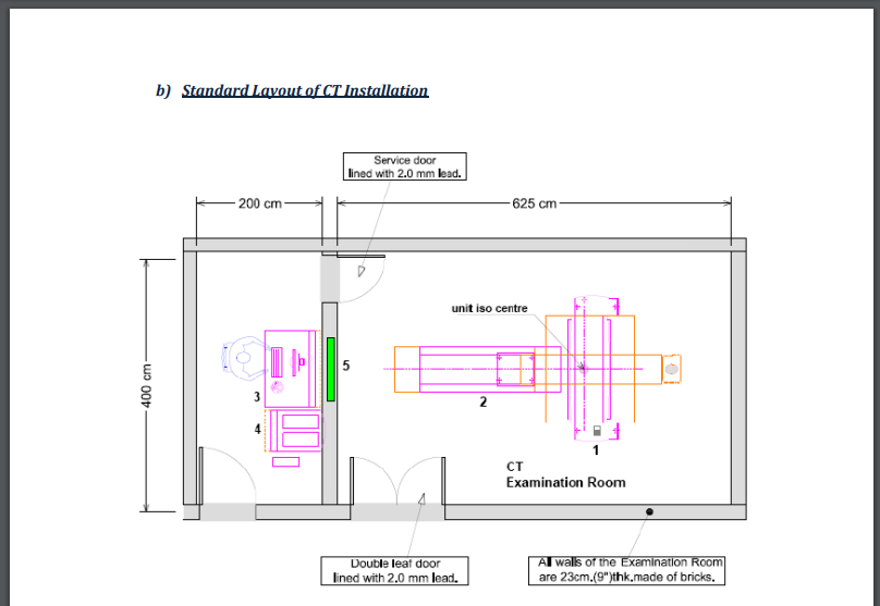
The Standard Layout of the CT Installation according to AERB rules.
- Double Leaf door lined with 2.0 mm lead.
- Service Door Lined with 2.0mm lead
- All walls of the Examination Room are 23cm(9”)thk made of bricks.
- Viewing Glass window 100cm X 80cm of 2.0mm lead equivalence.
- CT Gantry, Examination Table, 4 Control Unit.

CT Scan Machine Room Layout and Shielding Requirement
The Scan room should be typically around 27 feet by 15 feet in size and must be an open space for a table, scanner, room techs, and patients to move around.
- Existing facility– Addition of the CT Scan machine in the present space, you may need to relocate or add some extra space around 375-405 square feet.
- New Facility– If you are building the CT scan machine room at your place, it is important to consider the related rooms also. Includes Waiting areas, Offices, and other equipment rooms, for this, you need around 600-650 square feet.
A Closer Look at CT Scan Room Measurements
- The room housing CT Scan equipment shall have an appropriate area to facilitate easy movement of staff and proper patient positioning.
- Providing appropriate structural shielding for walls, doors, ceiling, and floor housing the X-ray equipment will keep radiation exposure minimal.
- The joints or discontinuities require a proper overlap of shielding materials
- Installation of Control Console of CT Scan Equipment should be in a separate room located outside, adjoining the CT Scan room.
- Providing it with the appropriate shielding, direct viewing, and oral communication facilities will help the operator and patient.
- The gantry and couch require to have a complete view of the patient from the viewing window.
- In case of a room housing radiography equipment, Place the chest stand in the X-ray room so no stray radiation reaches the control console entrance.
- Mobile X-ray equipment, when used as fixed X-ray equipment, shall comply with all the requirements of those of fixed X-ray installation.
- Pasting of the permanent radiation warning symbol and instructions for pregnant/likely-to-be pregnant women on the entrance door of the X-ray installation illustrates that the equipment emits radiation.

Step-by-Step Guidelines for Submission of Layout Plan in a diagnostic radiology facility.
1) Decide a suitable room for the CT Scan unit to facilitate the easy movement of staff and patient positioning.
2) Room should have preferably one entrance door and window if present, should be above 2m from the finished floor level outside the x-ray room.
3) Door should have a hydraulic mechanism to ensure that the closed door during the procedure and to avoid streaming providing overlapping at the joints.
4) Identify the walls as Wall A, Wall B, Wall C & Wall D (in any sequence).
Computed Tomography (CT) Scan Equipment
- Computed Tomography and Interventional radiology equipment: Gantry / C-Arm, Couch, Separate control console room, viewing window.
- Position the gantry and couch such that the patient is completely visible from the control console, during the scanning
- The entrance door to the gantry room from the control console shall have similar requirements as the patient entrance door.
- Decide on the material and thickness of walls and doors by referring to the equipment-specific table.
- Measure the distances of all the walls, doors, and windows from the center of the couch
- The required shielding of any material is at least up to the height of 2m from the external finished floor of the X-ray room.
Importance of Adequate Space for Medical Devices
- Sufficient space between magnetic fields generated by different electrical installations allows any diagnostic device, such as X-ray or radiography tools, to operate optimally without interference or hindering one another’s performance capability.
- It also ensures optimal privacy protection for patients since no overlapping audio/visual signals can occur inside a limited area with several emitters nearby each other.
Standard Sizes of the CT Scan Room
- 4 Slice – 8ft Width x 9ft Length at least
- 8Slice – 10 ft Width X 11 Ft Lenght at least
- 16 Slice – 12 ft width x 15 Feet length minimum
- 32 Slices – 16 feet width x 20 feet length minimum
- 64 slice – 18 feet (width) x 22 feet (length)
- 128 slice – 20 ft (width) x 25 ft (length)
The standard room size for CT scan machines can vary depending on the specific model and manufacturer. These dimensions are general guidelines and it is important to consult the specific manufacturer’s recommendations and procedures for the CT scanner being installed.
Need of Electricity for CT Scan Machine
CT scan machines are invaluable tools utilized by medical professionals to diagnose and monitor internal health issues. While they can provide detailed images of the body tissues, organs, and areas.
In order to function correctly and accurately, these scanners must draw large amounts of electricity from their local power grids.

To operate properly and safely, all electrical components must be within the stated requirements upon startup. Specifically checking frequency tolerances (60-400 Hertz) and voltage basics remain critical aspects during general testing such as line leakage and Current measurements.
Also checking frequency for hospital-specific tests like measuring EMI radiated noise levels inside an X-ray room while running various exams on different parts of the anatomy simultaneously at high-intensity settings.
Energy Requirements for CT Scan Machine
The modern healthcare industry relies heavily on machines to diagnose traumatic injuries or medical conditions. One such type of machine is the computed tomography (CT) scanner.
A sophisticated imaging device used in radiology departments worldwide to provide detailed cross-sectional images of complex bodily structures. – this article will discuss what exactly that energy demand entails.
What Power do CT Scanners Require?
Radiological departments are the major energy consumers within the hospital through the operation of CT Scan Machines. It requires energy in the range of 0.5-30 kWh per test/exam; with the peak consumption reaching beyond the 100 kW for a short time period.
– Usage of High-frequency power supplies in computed tomography (CT), provides stable tube currents and voltages.
– Modern CT scanners make use of slip ring technology that supplies high voltage to the tube through contact rings in the gantry.
–Voltages of the tube range from 80 to 140 kV.
–Currents of the tube can range up to 1,000 mA.
–Tube currents are frequently modulated as the X-ray tube rotates around the patient.
-It increases when the path length increases, as in a lateral abdominal projection compared to an anteroposterior (AP) projection.
Power Supply
- It requires a power supply – of 3 PHASES+G
200/220/240/380/400/420/440/460/480 V ± 10%
- Frequencies – 50/60 Hz ± 3 Hz
- Maximum Power Demand – 100 kVA
- Average (Continuos) Power Demand – 20 kVA
- Power Factor – 0.85 100 kVA (Kilowatt ampere)
- The power supply should come into the main disconnect panel(MDP) containing protective units and controls.
- In accordance with its length and maximum permissible voltage drops calculation of section of supply cable
- There must be discrimination between the supply cable protective device at the beginning of the installation (main low-voltage transformer side) and the protective devices in the MDP.

Supply Characteristics
- Power input must be separate from any others which may generate transients (elevators, air conditioning, radiology rooms equipped with high-speed film changers…).
- Separate power supply to all equipment installed within the system
- Phase imbalance 2% maximum.
- Transients must be less than 1500V peak. (on a 400V line)
Ground System
- System of equipotential grounding.
- Equipotential: The equipotential link will be by means of an equipotential bar.
- Connection of the equipotential bar to the protective earth conductors in the ducts of the non-GE cableways.
- In addition, equipotential connections link up all the conducting units in the rooms where there are system units.
Cables
- Power and cable installation must comply with the distribution diagram.
- Cable color codes must comply with standards for electrical installation and isolation of all cables.
- The cables from the signaling and remote control will go to MDP(Main Distribution Panel) with a pigtail length of 1.5m, connected during installation. Identification and isolation(screw connector) of each conductor.
Cableways
- The general rules for laying cableways should meet the conditions laid down in current standards and regulations, with regard to Protecting cables against water (cableways should be waterproof).
- Protecting cables against abnormal temperatures (proximity to heating pipes or ducts) and temperature shocks.
- Replacing cables (cableways should be large enough for cables to be replaced).
- Grounding of the metal cableways.
All wires specified shall be copper stranded, flexible, thermo-plastic, color-coded, cut 10 foot long at outlet boxes, duct termination points or stubbed conduit ends.
The electrical contractor shall ring out and tag all wires at both ends. Wire runs must be continuous copper stranded and free from splices.
Wiring Materials
1. No Aluminum or solid wires . Wire sizes given are for the use of equipment. Local codes may require a larger size.
2 . All wires be color coded, as required in accordance with national and local electrical codes.
3. Verification of conduit size by the architect, electrical engineer, or contractor.
4. Locate at least one convenience outlet close to the system control, the power distribution unit, and one on each wall of the procedure room. Use hospital approved outlet or equivalent.
5. To avoid excessive heat from overhead spotlights, be cautious. The use of high-voltage bulbs can damage ceiling mounting components and wiring.
Power Connections
1. Low-wattage bulbs no higher than 75 watts and use dimmer controls (except MR). Do not mount lights directly above areas where ceiling-mounted accessories will be parked.
2. Routing of cable ductwork, conduits, etc., must run directly as possible otherwise may result in the need for greater than standard cable lengths.
3. Conduit turns to have large, sweeping bends with minimum radius by national and local electrical codes.
4. Requirement of a special grounding system in all procedure rooms by some national and local codes.
5. Consult the governing electrical code and confer with appropriate customer administrative personnel to determine the areas requiring this type of grounding system.
6. Make a physical connection of primary power to the equipment by the customer’s electrical contractor with the supervision of a company representative. Requirement of the representative to identify the physical connection location and ensure proper handling of the equipment.
7. The company will conduct power audits to verify the quality of power delivered to the system. The customer’s electrical contractor must be available to support this activity.
Supply and installation of all junction boxes, conduit, duct, duct dividers, switches, circuit breakers, cable trays, etc. by the customer’s electrical contractor. Conduit and duct runs shall have sweep radius bends
Installation of the Conduits and ducts above the ceiling or below the finished floor as near to the ceiling or floor as possible to reduce run length.
AC (Alternating Currents) Requirements
- X-rays produced by the X-ray tube have a continuous wave pattern, which is an AC pattern moving in a sinusoidal waveform.
- The use of the AC pattern is to control the exposure parameters of the X-ray tube.
- It includes tube current (mA), and tube voltage (kVp) to produce images of varying quality.
- The rotating X-ray tube in CT scanning generates an alternating electromagnetic field that is detected by the detectors.
- The detectors convert the received radiation into electrical signals, to create high-quality images.
Grounding is critical to equipment function and patient safety. Site must conform to the wiring specifications.
Understanding the exact amount of power your CT Scan Machines need is essential not only for successful installation and operation but also for ensuring everyone involved with these devices has access to reliable information.
How much distance of transformer is required for CT Scan Machine Room?

Safety is an important consideration when placing a transformer near any type of medical equipment. This includes CT scan machines, which generate huge amounts of electromagnetic waves that can interfere with the power supply from a nearby transformer.
An adequate distance should be kept between the MRI or CT scan machine room and any outside electrical source.
Larger transformers require greater distances than smaller ones because large voltage fluctuations tend to increase their levels of interference with surrounding electronic systems such as medical imaging systems like those found in hospitals or clinics using X-ray machinery like Computed Tomography (CT) scans.
Distance
The maximum distance depends on the equipment that you are using, the chosen CT must be able to supply enough power with maintaining the accuracy.
Depending on which type of transformer you have installed and what machinery will be in use while scanning, This minimum clearance should help ensure both workers in the facility and patients are safely insulated from potential electric hazards while undergoing examinations or treatments using X-ray equipment like CT scans.
This ensures safe operation without interference from other high-voltage current sources nearby. It’s always best practice to double-check with local safety codes when installing electrical equipment near medical facilities as well.
Safety Codes
Safety Codes mean collectively The NEC(National Electrical Code), NESC( National Electrical Safety Code), and all other applicable regulatory codes for safe practices when performing work near the structure or Infrastructure.
Why Safety Codes are needed?
To protect the workers from occupational safety and health hazards and to prevent and reduce illness and injuries by providing practical guidelines.
If there are transformers inside building walls; where these kinds of transformers are externally mounted they need quite a higher insulation level compared to normal generators.
Voltage regulation within your respective country is crucial to protect the public while performing X-rays.
Correct setup procedures moving forward so scenarios remain safe manageable efficient times throughout the whole lifecycle provided specific parameters.
Distance Requirements Between Transformers & Diagnostic Rooms
– Before delving into suggestions about distances needed between two large pieces of medical machinery, one must first understand what types of equipment are involved.
– A transformer will convert line voltage or supply voltage into lower levels of energy while providing insulation so electricity can remain at one level to operate efficiently without suffering damage during transfer or storage.
– While exact measurements can vary according to several factors (width restrictions included) around specific locations (indoor versus outdoor spaces mentioned earlier), CT Scan machines require an adequate amount of space to operate safely and efficiently.
– The National Electrical Code calls for at least 25 feet (7.5 meters) of unobstructed space should be kept between any high voltage equipment – such as transformers – and medical imaging rooms, away from any closed surrounding walls or building systems, but it may vary depending on range and type of radiation being used.
Working Space (Electrical Unit)
It is also an important factor to consider. The following applies in the case of 0-600V installations: The below are given in feets
- 3 ft between insulated materials
- Between grounded equipment 3-½ feet
- 4 ft between exposed live parts
Electrical rooms must also have proper size entry and exit, which must be kept clear from obstructions at all times. If service capacity is greater than 1200 Amperes, the following requirements apply:
- Two exits must be provided.
- Doors located less than 25 feet from the working space must open in the exit direction and must be openable with simple pressure.
Risks associated with Not following Proper Safety Regulations
– Failure to adhere to these requirements can put hospital personnel as well as patients at risk due to possible overexposure resulting in both short-term health issues–like confusion—as well as long-lasting ones –such as cancer-related diseases.
– It could also lead to electric arches caused due to unwanted overloaded wire producing more heat than normal; in extreme cases, may produce fire which could damage multiple human lives and assets alike.
It is very important to find out what the regulations required based on your specific location and then decide on how much space is required between your CT scanner room and transformer installations/connections. Doing this will help you maintain safe operation standards as well as comply with government codes regarding electricity usage around sensitive equipment.

